






7 Best Plastic Injection Moulding Process Steps

Plastic injection moulding process control turns heated polymer into repeatable, saleable components. It remains central to automotive, medical, electronics, and consumer-product manufacturing. PlasticsEurope’s Plastics—The Fast Facts 2024 reports global plastics production reached 413.8 million tonnes in 2023. That scale creates pressure for tighter tolerances, shorter cycles, and less material waste. The mould may look like a simple steel block. It is not.

This guide examines seven practical steps: design validation, material selection, mould design, machine setup, injection, cooling and ejection, and quality inspection. Each step affects the next one. A poorly vented cavity can leave burn marks. Excessive injection speed may create flash. Uneven cooling can distort a part before anyone measures it. ISO 20457 provides guidance for tolerances on moulded plastic parts, but real production still requires engineering judgment and process trials.

Industry market studies from Grand View Research and MarketsandMarkets indicate continued expansion in injection moulding and related machinery, driven by lightweight components and automated production. However, growth does not make every mould efficient. That assumption deserves scrutiny. A faster cycle can increase defects, energy use, or maintenance costs. Reliable results come from recorded settings, validated materials, capable tooling, and inspection data. The following steps explain how experienced teams reduce uncertainty, identify weak points, and improve consistency from the first mould trial to stable production. Mistakes still happen. Good process control makes them visible early.
7 Best Plastic Injection Moulding Process Steps

Preparing the Mould Design and Plastic Material

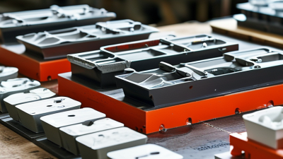
Preparing the mould design and plastic material sets the direction for every injection moulding step. A practical design review checks wall thickness, draft angles, cooling channels, gates, and ejector locations. Uniform walls usually reduce sink marks and warping. Sharp internal corners deserve attention. They can restrict material flow and increase stress.

Material selection must match the part’s working conditions. Consider heat, impact, chemical exposure, surface finish, and expected load. Moisture-sensitive plastics need controlled drying before processing. Otherwise, silver streaks or brittle areas may appear. Follow the resin supplier’s technical data, but verify it with trial shots. A datasheet cannot reveal every moulding issue.

Tips: Keep the first mould design simple. Use clear draft angles. Place gates near thicker sections when possible. Record drying temperature, time, and material batch. Do not guess.

A small test moulding can expose problems early. Check dimensions after cooling, not immediately after ejection. Shrinkage changes as the part settles. I have seen attractive samples fail because the designer measured only one cavity. Cavity balance, vent depth, and cooling symmetry also deserve inspection. Some designs look perfect on screen but need revision on the machine. That is normal. Careful notes from each trial improve the next adjustment and make production decisions more reliable.

Setting Up the Injection Moulding Machine

Setting Up the Injection Moulding Machine

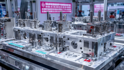
Setting up an injection moulding machine starts with a clean, stable workspace. Inspect the mould for damage, blocked vents, or leftover material. Secure it between the platens, then check alignment before applying full clamping force. A small alignment error can create flash along the parting line.

Load the approved material and dry it when required by its technical data. Set barrel temperatures gradually, rather than copying an old production record. Adjust screw speed, back pressure, injection speed, and cooling time to match the mould and resin. Keep hands away from moving areas, and verify guards, emergency stops, and temperature readings. The first trial shot is evidence, not proof. It may show short filling, sink marks, or a burn near the vent. Record each change carefully. In practice, settings are rarely perfect on the first attempt.

Tips: Purge the barrel until the melt looks consistent. Weigh several trial parts, not just one. Check dimensions after cooling, because warm plastic can mislead measurements. Watch the pressure curve for unusual peaks. If the machine sounds different, stop and investigate. A loose hose or blocked water channel can waste hours. Avoid raising pressure immediately; improving venting, drying, or temperature balance may solve the defect more safely. A simple setup checklist also helps, although experienced operators sometimes skip it and regret that decision.

Melting Plastic and Filling the Mould Cavity

Melting plastic and filling the mould cavity demand controlled heat, pressure, and timing. A typical injection unit heats pellets through several barrel zones. Shear from the screw adds more heat. The melt must become uniform, not simply hot. Excessive temperature can cause degradation, while insufficient heat creates unmelted particles and short shots. PlasticsEurope reported global plastics production at 400.3 million tonnes in 2022, showing the scale behind this manufacturing discipline (Plastics—The Fast Facts 2023). Grand View Research estimated the injection-m molded plastics market would grow at about 4.6% annually from 2023 to 2030. Small process errors can therefore become expensive quickly.

During filling, injection speed should match the cavity geometry. Thin walls usually need faster flow, but sharp speed changes may trap air or create weld lines. Operators monitor melt temperature, injection pressure, screw position, and the velocity-to-pressure transfer point. Proper venting helps air escape near the final filling area. A mould temperature that is too low may freeze the flow front early. Too high, and cycle time increases. I would not treat a standard setting as permanent. Resin moisture, batch variation, and ambient temperature can change the result. The process is less forgiving than it appears.

Tips: Dry moisture-sensitive pellets according to the material supplier’s specification. Check the actual melt temperature with a calibrated probe. Record pressure and shot weight for each setup. Start with moderate injection speed, then adjust after inspecting flow marks, flash, and part weight. A short shot is useful evidence, not just a failed part.

Cooling the Part and Opening the Mould

Cooling often controls the injection moulding cycle. Industry process benchmarks from the Society of Plastics Engineers commonly estimate that cooling consumes 50–70% of total cycle time. The mould should remove heat evenly, not simply quickly. Uneven cooling can create sink marks, internal stress, or visible warpage.

Use cooling channels close to thick sections, while keeping a safe distance from the cavity surface. Water temperature, flow rate, and pressure should be monitored at the inlet and outlet. A temperature difference above 2–3°C across the mould can indicate poor flow or blocked channels. These small changes matter. In production trials, I would record part temperature before ejection, rather than relying only on machine settings. The target ejection temperature depends on resin, wall thickness, and geometry. There is no universal number.

Tips: Keep the mould closed until the part has enough stiffness. Opening too early may deform ribs or polished surfaces. Check the first and last cavity parts separately. Cooling is rarely perfectly balanced, and that is worth admitting. If warpage appears, reduce the ejection temperature gradually and inspect the cooling circuit before changing packing pressure. Open the mould smoothly, with controlled movement. Ejector pins should advance evenly, leaving no white stress marks or drag lines. Data from each cycle helps distinguish thermal problems from mechanical faults.

7 Best Plastic Injection Moulding Process Steps - Cooling the Part and Opening the Mould
Step Process Stage Typical Process Data Key Quality Checks Common Risks and Controls
1 Material Preparation
  • Dry hygroscopic resins according to the material supplier’s specification.
  • Typical drying temperature: approximately 70–120°C for many engineering thermoplastics.
  • Non-hygroscopic materials may require only clean, sealed storage.
  • Confirm resin type, grade, and lot traceability.
  • Verify drying time, temperature, and moisture level where applicable.
  • Check that regrind content remains within the approved process limit.
Moisture can cause splay, bubbles, reduced strength, and hydrolytic degradation. Use a calibrated dryer and keep dried resin protected from ambient humidity.
2 Mould Setup and Preheating
  • Install and secure the mould according to the machine and mould specifications.
  • Set mould temperature commonly between 20–120°C, depending on resin and part requirements.
  • Check cooling-channel flow and hydraulic or electrical connections.
  • Confirm parting-line alignment and ejector operation.
  • Verify cavity pressure, temperature, and coolant connections are leak-free.
  • Check that the mould surface is clean and properly lubricated where permitted.
Uneven mould temperature may cause warpage, weld-line weakness, or inconsistent gloss. Balance cooling circuits and allow the mould to reach a stable temperature.
3 Filling and Injection
  • Inject molten polymer at a controlled speed to fill the cavity before premature freezing.
  • Typical melt temperatures range from approximately 180–330°C, depending on polymer type.
  • Use a controlled transfer from velocity to pressure near the end of filling.
  • Monitor short shots, flash, burn marks, and flow lines.
  • Check cavity-fill balance for multi-cavity moulds.
  • Record injection speed, transfer position, and peak pressure.
Excessive speed can create jetting, burn marks, or trapped air, while insufficient speed can produce short shots. Use venting and adjust the fill profile gradually.
4 Packing and Holding
  • Apply holding pressure after filling to compensate for material shrinkage.
  • Typical holding time is often a few seconds, but it must be established by part weight and gate-freezing studies.
  • Holding pressure is commonly lower than peak injection pressure.
  • Use a part-weight study to identify the gate-seal point.
  • Check sink marks, voids, dimensions, and weight consistency.
  • Confirm that the screw reaches a stable and repeatable recovery position.
Too little packing may cause sink marks or internal voids. Excessive pressure or time can cause flash, sticking, and residual stress.
5 Cooling the Part
  • Maintain cooling until the part is rigid enough for ejection without unacceptable distortion.
  • Cooling time commonly ranges from about 5–30 seconds for many small and medium parts, but thickness is the main driver.
  • Cooling-channel water is often controlled around 10–40°C, depending on resin and surface requirements.
  • Measure coolant inlet and outlet temperatures and flow rates.
  • Check part temperature, warpage, shrinkage, and dimensional stability.
  • Use balanced cooling near thick sections, ribs, bosses, and corners.
Early ejection can cause bending, dents, or deformation. Excessive cooling time reduces productivity. Optimize the cycle using thermal measurements and dimensional inspections.
6 Opening the Mould
  • Open the mould at a controlled speed after cooling and plasticizing are complete.
  • Set the opening stroke only high enough to clear the part and runner system.
  • Use a sufficient dwell or low-speed approach where parting-line protection is required.
  • Confirm that no part, runner, or insert remains trapped at the parting line.
  • Inspect for sticking, scuffing, flash, and mould damage.
  • Verify that core pulls and slides have completed their sequence before opening.
Excessive opening speed may damage the mould or deform the part. Incorrect sequencing can damage slides, inserts, or unscrewing mechanisms. Use interlocks and position sensors.
7 Ejection and Cycle Verification
  • Eject the part with the minimum force and stroke needed for reliable release.
  • Allow the part to cool further outside the mould when dimensional requirements permit.
  • Establish a repeatable total cycle time from mould close to the next mould close.
  • Inspect appearance, dimensions, weight, gate vestige, and ejector marks.
  • Check that the part is fully released before mould closing.
  • Record cycle time, reject rate, and critical process parameters.
Excessive ejection force can leave white marks, dents, or cracks. Incomplete ejection may cause mould damage during closing. Use adequate draft angles, balanced ejectors, and automated part-presence detection.

Removing, Inspecting, and Finishing the Moulded Product

Removing, Inspecting, and Finishing the Moulded Product

Once the injection cycle ends, allow the moulded part to cool evenly before ejection. Rushing removal can cause drag marks, distortion, or hidden stress near thin walls. Use the specified ejector sequence and support flexible areas when appropriate. Keep gloves clean. Fingerprints and dust can affect later inspection. Parts may look acceptable under workshop lighting, yet show faint flow lines beside ribs.

Inspection should combine measurement, touch, and visual comparison against the approved drawing or sample. Check dimensions at a stable temperature, especially around gates, corners, and deep bosses. Look for short shots, flash, burn marks, sink marks, warpage, and trapped particles. Record the cavity number, batch details, and defect location. This evidence helps separate mould problems from material, machine, or handling issues. Do not reject every unusual mark immediately. Some marks are harmless, but unsupported assumptions can create repeated failures.

Tips: Trim gates with a sharp, controlled tool, then remove burrs without rounding functional edges. Use suitable abrasives for visible surfaces, moving in one direction to maintain consistent texture. Clean each part and inspect it again after finishing. Avoid excessive polishing. It can change dimensions or expose fibres in reinforced materials. Store finished parts in clean containers with separators. If defects repeat, review ejection force, cooling balance, and finishing technique before increasing output.