






How to Choose the Best Super Finishing Process

Choosing a super finishing process is not a matter of chasing the lowest roughness number. The right method must suit the component, material, production volume, and required surface performance. A hardened bearing race, for example, may need a different approach from a hydraulic spool with fine cross-hatch requirements. Start with the part’s function, then define measurable targets for roughness, geometry, and material removal.

Grinding researcher Stephen Malkin’s work offers a useful way to frame the decision. In paraphrase: “Choose a finishing method by the surface and performance the part must deliver.” That is a practical principle, not a substitute for trials. A process that works on one alloy or geometry may disappoint on another. Small differences matter.

This guide compares common super finishing process options, including abrasive-belt, stone, and specialized vibratory methods. It explains where each can help, what equipment and setup may require, and which trade-offs deserve attention. Expect practical checks, too: inspect the contact pattern, verify coolant delivery, and measure parts under consistent conditions. Measurements can mislead when setups vary. Not every shop has ideal instruments or a perfect first run. Record what changes, review the results, and refine cautiously. The best choice balances surface quality with cycle time, cost, repeatability, and the component’s real operating demands.
How to Choose the Best Super Finishing Process

What Superfinishing Is and How It Works

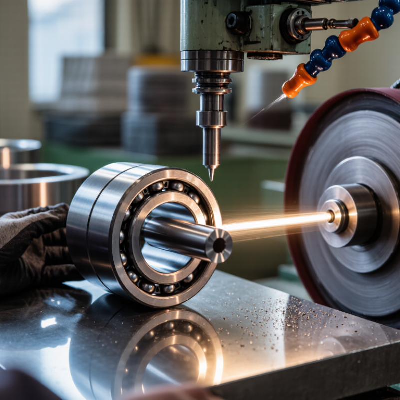
Superfinishing is a precision operation applied after grinding or another machining step. A fine abrasive stone contacts a rotating workpiece while moving rapidly back and forth. This combined motion creates a cross-hatched pattern and removes tiny surface peaks. It is not intended to reshape the part. The goal is a smoother, more consistent surface that supports reliable contact.

The process uses light, controlled pressure. Abrasive grains cut high spots, while lubricant or coolant carries away debris and limits heat. On a shaft, for example, the stone may travel across a journal as the shaft turns. The result depends on abrasive size, stone condition, oscillation, pressure, and cycle time. Small changes matter. Too little action may leave grinding marks; too much can alter dimensions or create an uneven finish. It is subtle.

Superfinishing is often used on bearing surfaces, seals, and other parts where friction, wear, or oil retention matter. Surface roughness alone does not tell the whole story; surface direction, roundness, and intended contact also need checking. A roughness reading can look excellent while a part still performs poorly. That is easy to miss. Process trials on representative material are more dependable than generic settings, since alloys, hardness, and prior grinding vary. Operators should check dimensions and surface texture at several points, especially near shoulders and edges.

Key Factors That Influence Superfinishing Results

Superfinishing results begin with the surface left by the previous operation. The process removes a small amount of material, so deep scratches or waviness may remain. Small changes matter. Material hardness, heat treatment, and part geometry also affect how an abrasive stone contacts the workpiece. A narrow journal, for example, may need different contact pressure from a broad flat surface.

Abrasive grit, bond, pressure, oscillation, and rotational speed work together. Finer grit can reduce roughness, but it may cut too slowly or load with debris. Coolant helps control heat and carry away swarf; poor filtration can let particles mark the finished surface. Not always. Increasing pressure is not a reliable shortcut, since it can cause uneven contact or unwanted geometry changes.

Define the target before adjusting the process: surface roughness, roundness, size, and functional performance may not improve at the same rate. Check parts at consistent locations and use the same measurement method, because a single roughness reading can miss directional marks. Trial runs on representative material help reveal the useful process window. The awkward part is that small batches may behave differently from production runs, so settings still need verification under actual conditions.

How to Compare Superfinishing Methods and Equipment

How to Choose the Best Super Finishing Process
How to Compare Superfinishing Methods and Equipment

Compare processes against the part, not a brochure specification. Stone superfinishing can suit controlled contact on cylindrical surfaces, while abrasive tape may reach narrow or changing profiles. The best fit depends on material hardness, geometry, starting roughness, and required stock removal. A very low Ra reading is not enough if roundness or edge condition suffers.

Assess the equipment using measurable settings: contact pressure, oscillation, spindle speed, feed rate, and coolant delivery. Ask whether the machine holds these settings consistently across a full production run. Compare cycle time, setup changes, abrasive life, operator access, and inspection needs. Use the same material batch and starting condition for trials. Measure Ra and Rz, but also check size, form, and visible defects. One successful sample can mislead.

Tips: Keep a few parts from each trial for repeat inspection. Record settings beside the results. If one method wins only at a very slow feed, question its production value. Tool access may be awkward. That matters. Leave room for a second trial; real components rarely behave exactly like the sample.

How to Choose the Best Super Finishing Process – How to Compare Superfinishing Methods and Equipment
Method and Typical Equipment How It Works Suitable Workpieces Main Advantages Limitations and Considerations Best Fit When…
Oscillating stone superfinishing
Rotating spindle with reciprocating abrasive-stone head
A fine-grain stone is pressed against a rotating surface while moving back and forth over it. The short oscillating motion creates a cross-hatched surface texture. Cylindrical shafts, bearing journals, rollers, and selected bearing raceways. Provides precise, localized contact; works well on cylindrical surfaces; can improve surface texture while retaining the underlying geometry when setup and stock removal are controlled. Requires suitable tooling and alignment for each part geometry. Stone loading, dressing, contact pressure, and workpiece runout need to be managed. The part has accessible cylindrical surfaces and consistent finishing of journals or raceways is the priority.
Abrasive-tape superfinishing
Tape head with controlled feed and contact shoe or roller
A supported abrasive tape contacts a rotating workpiece and advances to expose fresh abrasive. Contact force and tape feed are controlled by the machine. Shaft journals, camshaft features, rollers, and other accessible external cylindrical surfaces. Fresh abrasive is continuously presented; tape can reduce the effects of abrasive loading and can be practical for automated, repeatable production. Tape width, backing flexibility, contact support, and feed settings affect the result. It is generally less suited to features that the tape cannot reach or support consistently. Repeatable finishing of external cylindrical areas is needed, especially in an automated production line.
Abrasive-belt finishing
Belt machine with contact wheel, shoe, or platen
A moving abrasive belt contacts the workpiece through a wheel or support surface. Depending on the abrasive and setup, it can remove more material than a fine finishing pass. Accessible shafts, bars, flat areas, and selected formed surfaces. Can cover larger contact areas and support relatively high material-removal rates. Belt changes can provide a practical way to move between abrasive grades. Contact pressure and belt tracking influence dimensional accuracy and edge shape. Excessive removal can alter geometry or generate heat, so it may not suit very tight finishing allowances. Broader surfaces or higher throughput are important and the part can tolerate the chosen contact method and removal rate.
Face or end-face superfinishing
Rotating workholding with flat stones, segments, or abrasive tooling
Abrasive tooling contacts a rotating flat or near-flat face. The machine controls the relative motion, pressure, and abrasive contact across the surface. Thrust faces, washers, bearing faces, and other accessible flat or annular surfaces. Designed for face geometry that is difficult to finish effectively with a cylindrical stone setup; tooling can be arranged to cover an annular or planar area. Flatness, parallelism, and face geometry depend on machine condition, fixturing, tool layout, and process control. Complex features may require custom tooling. The main functional surface is a flat or annular face rather than an external cylindrical surface.
Through-feed stone finishing
Continuous-feed machine with opposed or supported finishing tools
Parts move continuously through the finishing zone while abrasive tools contact the specified surfaces. The process is arranged around a consistent part size and geometry. High-volume production of compatible rollers, pins, or other parts that can be fed consistently. Supports continuous production and consistent cycle flow when parts are uniform and the machine is properly set up. Part geometry, size variation, and feeding orientation must be compatible with the machine. Changeovers can require tooling and setup adjustments. Production volume is high and workpieces can be reliably fed through a fixed finishing arrangement.
Plunge or oscillating plunge finishing
Stationary or reciprocating tool head acting on a held workpiece
The workpiece is positioned in a fixture and the abrasive tool engages a defined area. The tool may oscillate, while the workpiece remains located in the same position. Specific journals, narrow lands, or localized features that need controlled contact. Allows attention to a defined feature and can suit parts that are difficult to feed through a continuous process. Cycle time and tool access depend on the number and position of features. Fixturing must locate the part accurately and avoid marking finished areas. Only selected zones need finishing, or the part geometry calls for individual, controlled engagement.
Selection note: Compare methods using the required surface texture, dimensional and form tolerances, material and hardness, feature access, production volume, cycle time, abrasive life, and changeover needs. Surface-finish results depend on the starting surface, abrasive specification, machine condition, contact pressure, speed, lubrication or coolant, and process settings; validate the chosen process on representative parts and measure results against the drawing requirements.

How to Match a Superfinishing Process to Part Requirements

A superfinishing process should match the part’s function, not just a target roughness value. A shaft running inside a bearing may need a smooth, consistent surface that limits friction and wear. A sealing surface may demand controlled texture to retain lubricant without creating leak paths. Ra helps, but it cannot describe every feature of the surface. Specify the required texture, direction, and functional contact conditions where possible.

Part geometry and material narrow the options. Abrasive tape can work well on accessible cylindrical surfaces, while honing stones suit some bores and provide controlled contact. Hardness, starting finish, and the amount of material to remove also matter. Superfinishing typically removes a small amount; it will not reliably correct major taper, waviness, or out-of-roundness. That matters. A deep groove on a narrow journal, for example, may need a different tool path than a broad, uniform surface. Production volume and setup time count too, though they can be easy to underestimate.

Before committing, test the process on representative parts and measure more than Ra. Check dimensions, surface direction, and performance under the intended contact conditions. A profilometer reading is useful, but the first trial may still miss the functional target. Not always. Review the results with the designer or quality team, then adjust abrasive type, pressure, speed, or cycle time.

How to Verify Process Performance and Surface Quality

A super finishing process should be judged against the part’s function, not appearance alone. Set measurable targets for roughness, roundness, and dimensional change before trials begin. Record the incoming surface condition too. A shaft that looks bright may still have directional scratches or uneven contact bands. Define the inspection area and measurement direction, since readings can shift when the probe crosses the lay.

Use calibrated instruments and repeatable methods. A profilometer can measure Ra and Rz, while roundness equipment checks form on bearing surfaces. Inspect several locations, not just the easiest spot. Keep conditions fixed. Note the abrasive type, pressure, cycle time, and part temperature for each test batch. Small differences matter. It is easy to blame the process when inconsistent setup caused the variation.

Confirm results on multiple parts, including pieces from different production runs. Compare measurements with the drawing and functional requirements, then check for defects such as smeared material, edge rounding, or isolated deep marks under suitable lighting. A single excellent sample proves little. Track variation over time and retain inspection records so operators can spot drift. One limitation is that roughness numbers do not describe every surface feature; visual inspection and functional testing may still be needed. That extra check can feel slow, but skipping it leaves a gap.