






How to Measure Surface Roughness Accurately?

Accurate surface roughness measurement begins with a controlled process, not a single instrument reading. A polished metal sample may look smooth under bright light, yet reveal sharp peaks through a calibrated stylus. Small errors matter. Dust, vibration, temperature, and an unsuitable cutoff length can change the result significantly.

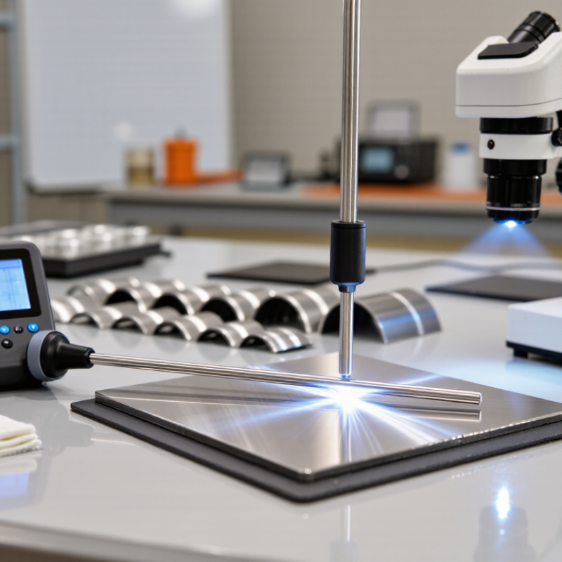
In practical workshop testing, I first clean the surface with a lint-free cloth and inspect its lay direction. The measuring instrument must be calibrated with a certified roughness specimen before testing. Its probe should move across the surface, rather than along the machining marks. This approach helps capture the real profile instead of hiding directional variation. Parameters such as Ra, Rz, evaluation length, and cutoff wavelength should match the drawing, specification, or applicable ISO guidance.

Do not trust one number blindly. Repeat measurements at several positions, especially when grinding, turning, or coating creates uneven textures. Record the instrument model, probe condition, filter settings, environmental conditions, and measurement direction. These details make results easier to verify and compare.

Some surfaces remain difficult. Curved parts, soft coatings, deep grooves, and reflective finishes may require optical methods or special fixtures. Optical systems reduce contact damage, but they can misread steep slopes or highly reflective areas. Contact instruments have their own limitations. No method is flawless.

A reliable report should explain uncertainty, not hide it. If repeated values differ widely, investigate the surface and the method before reporting an average. Accurate measurement is partly technical skill and partly disciplined doubt. That last part is often overlooked.
How to Measure Surface Roughness Accurately?

Define Ra, Rz, and Rt Under ISO 21920 and ASME B46.1

How to Measure Surface Roughness Accurately?

Surface roughness numbers only become meaningful when their rules are fixed. Under ISO 21920-2:2021, Ra is the arithmetic mean of the absolute profile deviations from the mean line. It is calculated across the selected evaluation length. A smaller Ra usually indicates a smoother surface, but it can hide isolated damage. One deep scratch may barely change the average.

Rz describes the maximum profile height, normally calculated from individual sampling lengths and then averaged. Rt is the total profile height across the entire evaluation length. It uses the highest peak and deepest valley.

ASME B46.1-2019 uses closely related concepts, yet parameter settings and reporting conventions can differ. Therefore, “Rz 6.3 µm” is incomplete without the standard, cutoff, filter, evaluation length, and measurement direction.

Consider a measured trace with Ra at 0.80 µm, five Rz values from 4.1 to 7.8 µm, and Rt at 12.6 µm. The wide spread suggests sporadic peaks or valleys. I would inspect the raw profile before accepting the result. ISO 21920-3:2021 emphasizes consistent instrument conditions and filtering, while ISO/IEC Guide 98-3 requires uncertainty evaluation. In practice, probe radius, vibration, contamination, and operator alignment can alter readings. A clean-looking number is not necessarily a reliable number.

Match the Cutoff Length: 0.08, 0.25, 0.8, or 2.5 mm

Accurate surface roughness measurement begins with the cutoff length. It is not merely an instrument setting. The cutoff separates roughness from longer-wavelength waviness, so an unsuitable value can change the reported result significantly.

ISO 21920-3:2021 and ASME B46.1-2019 recognize common cutoff lengths of 0.08, 0.25, 0.8, and 2.5 mm.

0.08 mm Use 0.08 mm for very fine surfaces, such as carefully finished sealing faces.
0.25 mm Choose 0.25 mm for finer machined surfaces.
0.8 mm The 0.8 mm setting suits many conventional turned or milled parts.
2.5 mm Use 2.5 mm when broader tool marks or coarse textures dominate.

The correct choice still depends on the expected Ra or Rz range and the manufacturing process.

Keep the evaluation length visible in the inspection plan. ISO measurement practice commonly uses five sampling lengths; with a 0.8 mm cutoff, that means a 4 mm evaluation length.

Clean the surface, align the stylus with the dominant lay, and verify the calibration before testing. Small details matter. A 90-degree alignment mistake can distort the result. The shortcut is tempting, but questionable.

ISO 4288 provides traditional selection guidance, while newer ISO 21920 documents clarify profile parameters and filtering. These standards offer authority, not certainty.

Surface texture can vary across one component, and operator judgment still affects the measurement. When results look surprising, repeat the test at several locations and record the cutoff used.

Calibrate the Instrument with a Certified Roughness Standard

How to Measure Surface Roughness Accurately?

Calibrate the Instrument with a Certified Roughness Standard

Accurate surface roughness measurement begins before the probe touches the workpiece. Use a certified roughness standard with documented values and traceable calibration records. Check its certificate date, assigned roughness parameters, and measurement direction.

Keep it clean. Dust, oil, or fingerprints can change the contact between the stylus and reference surface. Wipe the standard gently with a suitable lint-free cloth. Inspect the stylus tip for damage, then allow the instrument to reach room temperature. Temperature changes can affect both the instrument and the standard.

Place the standard on a stable, vibration-free surface. Align the measurement path with the certified direction marked on the standard. Take several readings, not just one. Compare the average result with the certified value and record the deviation. If the error exceeds the permitted tolerance, stop production measurements and investigate the cause.

A zero check is useful, but it does not replace calibration. Operators should also verify cutoff length, evaluation length, filter settings, and probe force. These settings must match the measurement procedure. In practical inspections, incorrect cutoff selection often creates a convincing but misleading result.

Do not rush. Repeat the test after cleaning the stylus and standard. Keep the calibration record with the instrument identification, date, operator, environmental conditions, and results. A small deviation may seem harmless, yet repeated measurements can reveal a developing instrument problem. One imperfect reading is a warning, not proof of failure. Rechecking is part of reliable measurement.

Measure Five Sampling Lengths Perpendicular to the Dominant Lay

How to Measure Surface Roughness Accurately?

Accurate roughness measurement starts with the correct direction. Identify the dominant lay, which is the visible pattern left by machining, grinding, or polishing. Move the stylus perpendicular to this lay. This path crosses the surface grooves instead of following them. A parallel trace can produce an artificially low reading.

Measure five sampling lengths within one evaluation trace. Keep the probe centered on a representative area, away from edges, holes, scratches, and visible damage. For example, on a turned shaft, avoid the shoulder and measure across the repeated tool marks.

Clean the surface with a lint-free cloth, but do not polish away small features. Use the specified cutoff, tracing speed, probe force, and tip radius for the material and drawing requirement.

Repeatability matters. Record the measurement direction and instrument settings with every result. If the five sections vary sharply, inspect the surface again rather than averaging blindly. The variation may indicate chatter, tool wear, vibration, or contamination. I have seen clean-looking parts produce unstable values when the stylus crossed a damaged edge. That mistake is easy to miss.

Use a second direction only when the lay is uncertain or multidirectional. A short visual inspection, supported by magnification, can prevent a misleading measurement. Do not report a single number without its parameter, such as Ra or Rz, and its evaluation conditions. Surface texture is not fully described by one value.

Report Ra in µm with Filter, Cutoff, Evaluation Length, and Uncertainty

How to Measure Surface Roughness Accurately?

A reliable Ra result begins with controlled measurement conditions. Clean the surface, remove loose particles, and align the instrument with the dominant lay. A small angular error can change the reported value. I have seen a machined surface report 0.82 µm Ra, then shift to 1.10 µm after poor alignment.

Report Ra in micrometres, not as an unexplained number. State the filter type, cutoff length, evaluation length, and measurement direction. ISO 16610 defines profile-filtering principles, while ISO 21920-3 addresses surface-texture specification and assessment. A five-cutoff evaluation length remains common in established practice, but the drawing or applicable standard should control. For example: Ra 0.82 µm, Gaussian filter, 0.8 mm cutoff, 4.0 mm evaluation length, measured perpendicular to lay.

Uncertainty deserves equal attention. NIST Technical Note 1297 recommends combining relevant uncertainty components, including calibration, repeatability, resolution, and surface variation. If the combined standard uncertainty is 0.05 µm, an expanded uncertainty near 0.10 µm may be reported with a coverage factor of two. That number is not decorative. It can decide whether a 0.80 µm requirement is truly met. Repeat the trace at several locations, especially near tool marks or edges. One reading is convenient, but rarely convincing. Some reports still omit cutoff settings. That omission should be challenged.

How to Measure Surface Roughness Accurately? — Report Ra in µm with Filter, Cutoff, Evaluation Length, and Uncertainty
Surface ID Surface Description Filter Cutoff λc Evaluation Length Measured Ra Measured Rz Expanded Uncertainty
(k = 2)
Measurement Result
Measurement Conditions and Surface-Roughness Results
S-01 Fine turned steel surface Gaussian profile filter 0.80 mm 4.00 mm
(5 × λc)
0.82 µm 4.65 µm ±0.08 µm Ra reported
S-02 Milled aluminum surface Gaussian profile filter 0.80 mm 4.00 mm
(5 × λc)
1.64 µm 9.12 µm ±0.14 µm Ra reported
S-03 Ground steel surface Gaussian profile filter 0.25 mm 1.25 mm
(5 × λc)
0.21 µm 1.38 µm ±0.03 µm Ra reported
S-04 Face-milled stainless steel Gaussian profile filter 2.50 mm 12.50 mm
(5 × λc)
3.28 µm 18.74 µm ±0.29 µm Ra reported
S-05 Polished stainless steel Gaussian profile filter 0.08 mm 0.40 mm
(5 × λc)
0.06 µm 0.42 µm ±0.01 µm Ra reported
Recommended Reporting Information
Primary parameter Report the arithmetic mean roughness as Ra in µm. Do not report the numerical value without its measurement conditions.
Filter and cutoff State the profile filter type and cutoff wavelength λc. The cutoff should match the surface texture and the applicable measurement procedure.
Evaluation length Use the evaluation length explicitly. A common convention is five sampling lengths, expressed as ln = 5 × λc.
Measurement direction Take the trace perpendicular to the dominant lay whenever the objective is to characterize the machining texture.
Uncertainty statement Report expanded uncertainty in the same unit as Ra and identify the coverage factor. The values above use k = 2, corresponding approximately to a 95% coverage probability.
Example report format Ra = 0.82 ± 0.08 µm (k = 2), Gaussian filter, λc = 0.80 mm, ln = 4.00 mm.