




How to Choose the Right Injection Mold Inserts

Choosing the right injection mold inserts can shape part quality, cycle time, and maintenance costs. The decision starts with the part, not a catalog. Review its geometry, resin, production volume, and expected surface finish. A thin rib, for example, may need different cooling and wear considerations than a broad, flat wall.

Material selection matters. Hardened tool steels can suit demanding production, while other alloys may fit lower volumes or specific thermal needs. The best option depends on the application. Check resin abrasiveness, operating temperatures, corrosion risks, and planned service intervals before specifying an insert. Also confirm that the mold design allows practical access for inspection and replacement. Small details matter.

There is no universal insert that works for every mold. A choice that improves heat transfer may complicate machining or raise costs. That trade-off deserves attention. Compare supplier data with actual process conditions, and ask how performance was tested. Where possible, review sample parts or trial results before committing to a design. One overlooked issue is often maintenance access; it can turn a minor repair into significant downtime. This guide explains how to assess fit, material, cooling, precision, and serviceability. It also notes where assumptions should be checked against production evidence. A careful selection process will not remove every risk, but it can make performance more predictable.
How to Choose the Right Injection Mold Inserts

Define the Function and Type of Injection Mold Insert

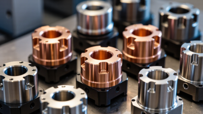
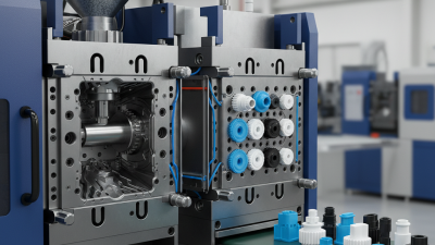
Define the insert’s job before choosing its material or shape. A mold insert is a replaceable section of the tool that forms a specific surface or feature. Core inserts shape internal details; cavity inserts form external surfaces. Wear inserts protect areas exposed to repeated sliding, sharp edges, or abrasive resin. These are different from metal inserts molded into the finished part. That distinction matters.

Start with the part drawing. Identify the feature, its tolerance, surface finish, and expected maintenance access. A narrow rib may need a small, replaceable core insert; a broad cosmetic face may call for a carefully polished cavity insert. If cooling is the priority, consider an insert designed around the local heat load, then verify its temperature behavior in trials.

The MarketsandMarkets report Injection Molding Market—Global Forecast to 2028 projected growth from USD 284.5 billion in 2023 to USD 369.2 billion by 2028. That forecast is market context, not proof that any one insert design is right.

Still, growing production can make downtime and replacement access more consequential. I find this easy to overlook: specifying a tough insert without planning how to remove it can complicate routine maintenance. Match the insert’s function to the failure risk, resin, cycle demand, and available service space. Then confirm the choice with toolmaker review and molding tests.

Assess Part Geometry and Operating Conditions

A mold insert should match the part’s geometry, not just its outline. Check thin ribs, deep cores, sharp corners, and tight shutoffs. These features affect filling, cooling, ejection, and wear. A narrow rib may need a durable insert, but a hard-to-cool core may call for better heat transfer. One choice rarely solves both.

Operating conditions matter just as much. The Society of Plastics Engineers’ Injection Molding Handbook indicates that cooling can account for roughly 70–80% of a molding cycle. That makes insert temperature control important, especially around thick sections and deep pockets. Compare resin processing temperatures, expected shot volume, cycle rate, and abrasive or corrosive fillers. Then check whether the insert can withstand clamp pressure and repeated thermal expansion without shifting or cracking.

Measure the actual part and inspect the tool, rather than relying only on CAD. A few tenths of a millimeter can change venting or shutoff contact. Small details matter. Document hot spots, flash, and wear during trials, and revisit the insert material if these appear early. I would not assume a higher-hardness material is automatically better; it may resist wear but conduct heat less effectively. That trade-off deserves testing under real production conditions.

How to Choose the Right Injection Mold Inserts - Assess Part Geometry and Operating Conditions

Assessment Factor What to Check Insert Selection Considerations Practical Guidance
Part geometry and detail Small ribs, lettering, sharp corners, deep features, or areas with tight dimensional tolerances. Consider a replaceable insert for localized details that may need polishing, adjustment, or repair. Choose an insert material and hardness appropriate for the detail and expected wear. Avoid unnecessarily thin or unsupported insert sections. Check for adequate backing, fit, and resistance to movement under injection pressure.
Undercuts and side actions Features that prevent straight mold opening, such as side holes, hooks, or transverse slots. Use an insert where a localized shutoff, lifter, or slide-forming feature can be made and maintained independently of the main cavity. Confirm release direction, clearance, shutoff contact, and access for maintenance. The insert must not create a trapped feature or interfere with ejection.
Resin and abrasive fillers Resin type and whether it contains glass fiber, mineral filler, or other abrasive additives. Abrasive compounds can wear cavity surfaces and gates faster. Select an insert steel, hardness, and surface treatment suited to the resin and production conditions. Base material and heat treatment matter; coatings are not a substitute for adequate substrate strength or correct processing. Verify compatibility before specifying a coating.
Corrosion and resin chemistry Moisture-sensitive resins, corrosive additives, flame retardants, or gases and by-products generated during molding. For corrosive service, consider corrosion-resistant mold materials or suitable protective treatments for the insert and adjacent surfaces. Check resin supplier processing guidance and cleaning requirements. Corrosion resistance should include exposed surfaces, cooling passages, and interfaces where moisture may collect.
Operating temperature and thermal cycling Melt and mold temperatures, cycle frequency, and temperature variation across the insert. Choose material and heat treatment that retain suitable strength and dimensional stability at the intended operating temperature. Account for thermal expansion and the fit between the insert and mold base. Check for hot spots, cracking risk, and changes in dimensions during operation.
Cooling and heat transfer Distance to cooling channels, local wall thickness, and whether the feature is prone to slow cooling or uneven shrinkage. An insert can provide a practical way to bring cooling closer to a localized hot spot or to replace a component with complex cooling needs. Maintain adequate material between cooling passages and cavity surfaces. Evaluate temperature uniformity and leak risk before adding or relocating passages.
Production volume and expected wear Expected shot count, run length, resin abrasiveness, and the cost or impact of unplanned downtime. For high-wear or frequently serviced areas, a replaceable insert can simplify repair and reduce the need to rework a larger mold section. Compare the insert’s initial cost with inspection, replacement, and downtime needs. Set an inspection interval based on observed wear rather than a universal shot-count threshold.
Parting line, vents, and shutoffs Flash-sensitive edges, air-trap locations, vent paths, and the location of insert joints relative to the part surface. Position insert boundaries where they can be fitted and maintained without compromising critical cosmetic or sealing surfaces. Specify fit and shutoff requirements clearly. Poorly controlled gaps can cause flash, resin leakage, or trapped gas.
Maintenance and changeover Tool access, insert retention, repeatability after removal, and the time available for cleaning or replacement. Use clear locating features and secure retention where frequent removal is expected. Design the insert so it can be inspected and installed without damaging adjacent surfaces. Document orientation, fit, and installation requirements. Confirm that fasteners or retention features remain accessible during routine maintenance.

Compare Insert Materials and Surface Treatments

P20 and H13 suit different insert conditions. P20 is commonly supplied at about 28–32 HRC, while heat-treated H13 often reaches roughly 44–52 HRC. These typical ranges are reported in ASM Handbook, Volume 1; actual values vary with grade and heat treatment. P20 is easier to machine for general-purpose inserts. H13 better tolerates heat and repeated thermal cycling, though it can cost more to machine. For corrosive resins or frequent cleaning, consider corrosion-resistant steel. Hardness alone is not a selection method.

Surface treatment should match the failure you expect. Nitriding creates a hard surface layer that can reduce wear, while leaving the core tougher than a fully hardened insert. PVD coatings can lower friction and help with abrasive or glass-filled resins. Polishing matters, too: a mirror finish may aid release on visible parts, but it will not fix poor venting or an unsuitable resin. I have seen teams specify a coating before checking the actual wear pattern. That order can waste time.

Tips: Check resin, cycle temperature, and expected production volume before choosing. Ask for hardness and coating-thickness records, then test a sample insert. A small trial often reveals what a datasheet misses.

Check Fit, Retention, Cooling, and Replaceability

Choose inserts by checking the actual steel-to-steel fit, not just the drawing. Measure the pocket and insert, then check for rocking, proud edges, and gaps after seating. Even a small mismatch can create flash or damage the pocket. Retention must resist injection pressure and repeated opening, while still allowing controlled removal. A shoulder, clamp, or screw may work; the right choice depends on access and load direction. Keep fasteners clear of the parting line.

Cooling deserves equal attention. Plastics Technology’s injection-molding cycle-time guidance places cooling at roughly 70–80% of a typical cycle, though resin, wall thickness, and mold design change the figure. That is a large window. Check whether insert channels can be drilled, cleaned, and sealed without weakening the insert. Compare temperatures near the cavity, not only at the manifold; a hot spot beside a steel insert can distort the part even when the outlet water feels cool.

Plan replacement before production. Use repeatable locating features and accessible fasteners, and record insert dimensions, material, and cooling layout. A spare insert is useful only if it fits without hand-filing. That detail gets missed. I would also question any design that requires removing half the mold for one wear component; it may save space on paper, but makes routine maintenance slower.

Verify Insert Performance Through Testing and Maintenance

An insert can look sound on the bench and still shift under production heat. Before a full run, check its dimensions, seating, and surface condition against the drawing. Record cavity temperature, cycle time, and any pressure settings used during the trial. Small changes can affect fit. That matters.

During a mold trial, inspect sample parts for flash, short shots, uneven texture, and dimensional drift. Measure critical features with suitable gauges, and compare results across several cycles rather than relying on one good part. Watch for discoloration or unusual wear around sharp edges. If defects appear, check alignment and cooling conditions before changing the insert; several factors may produce similar symptoms.

Maintenance should follow observed wear and the insert’s operating conditions, not just a fixed calendar. Clean contact surfaces with materials that will not scratch them, then inspect for burrs, cracks, corrosion, and loose seating. Keep a simple log of cleaning, measurements, repairs, and replacements. A checklist helps, but it cannot catch everything. Inspection intervals may need adjustment after the first production runs, and assumptions about expected tool life should be reviewed when actual wear tells a different story.