





How to Choose the Right Plastic Injection Moulding Process
Choosing the right plastic injection moulding process can shape a part’s cost, quality, and production schedule. The best option depends on more than the resin or machine size. Part geometry, annual volume, dimensional tolerances, and surface finish all matter. A thin-walled housing, for example, may need different tooling and process controls than a thick connector with metal inserts.
This guide compares common approaches, including conventional injection moulding, insert moulding, and overmoulding. It explains how material behavior, gate placement, cooling, and tooling complexity affect the finished part. A sharp corner or uneven wall can cause defects such as sink marks or warpage. Small details matter.
The right plastic injection moulding process should fit both the product and its expected production life. A simple single-material design may suit a standard mould, while bonded materials can require tighter control and additional setup. Higher output can justify more complex tooling, but only when demand supports the investment. Estimates are useful, not final. Tool trials may reveal changes that drawings alone cannot predict, and early cost comparisons can miss maintenance or scrap rates. That is worth reviewing.
Reliable decisions come from checking requirements with experienced moulders and validating critical features through prototypes or production trials. No process is ideal for every part. The goal is a practical balance between performance, repeatability, lead time, and cost—based on evidence, not assumptions.
Define Part Requirements and Production Objectives
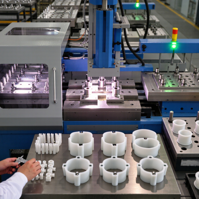
Define part requirements and production objectives before comparing plastic injection moulding processes. Record the resin, part dimensions, wall thickness, tolerances, surface finish, and any inserts. A thin rib beside a thick boss can create uneven cooling and sink marks. Specify which surfaces are cosmetic and which dimensions affect assembly. Small details matter.
Set expected annual volume, launch timing, acceptable scrap rate, and target unit cost. Grand View Research estimated the global injection-molded plastics market at USD 330.41 billion in 2023, with a projected 4.6% compound annual growth rate from 2024 to 2030. This market estimate signals broad industrial demand, but it does not determine the right process for an individual part. Still, forecasts do not design parts. A short run may not justify a complex multi-cavity tool, while high, steady demand can make faster cycles and added tooling investment worthwhile. Compare prototypes and production samples against the same measurable criteria. A specification can still miss something: teams sometimes overlook how a textured finish changes release behaviour. Revise the requirements when test results expose that gap.
| How to Choose the Right Plastic Injection Moulding Process - Define Part Requirements and Production Objectives | |||||
|---|---|---|---|---|---|
| Process option | Part requirements it suits | Production objectives it supports | Typical materials or features | Key design and tooling considerations | Best-fit decision signal |
| Conventional injection moulding | Rigid, repeatable parts with defined geometry, consistent wall sections, and moderate-to-complex features. | Repeat production at medium to high volumes; efficient cycle times once the mould is validated. | Common thermoplastics such as PP, ABS, PE, PC, PA, and POM; ribs, bosses, snap-fits, and living hinges where material-appropriate. | Account for draft, shrinkage, gate location, parting lines, ejection, and uniform wall thickness. Tooling investment can be substantial. | Choose when the design is stable and expected lifetime volume can justify a dedicated mould. |
| Thin-wall injection moulding | Lightweight parts with thin, relatively uniform walls and limited flow length relative to wall thickness. | High-volume production where reduced material use and short cooling time are priorities. | Often used with flow-capable thermoplastics, including polypropylene and some ABS grades; packaging and lightweight housings. | Requires careful flow, venting, gate, and cooling design. High injection speed and pressure may be needed; validate filling and warpage early. | Choose when weight and material savings matter and the machine, mould, and material can support fast filling. |
| Gas-assisted injection moulding | Thicker sections, long flow paths, or parts where sink marks and internal weight are concerns. | Reduce material use and part weight while maintaining stiffness in selected sections. | Typically thermoplastics compatible with the selected gas-assist process; hollowed ribs, handles, and large structural sections. | Requires gas delivery and process control, plus mould features designed for gas penetration. Surface appearance and gas paths need validation. | Consider when a conventional solid section is heavy or prone to sink, and the geometry can accommodate a controlled hollow core. |
| Insert moulding | Parts that permanently combine moulded plastic with a pre-placed component. | Consolidate assembly steps and create an integrated part in a single moulding operation. | Metal pins, threaded inserts, contacts, bushings, or other compatible components encapsulated or retained by plastic. | Design for insert retention, thermal compatibility, accurate placement, and repeatable loading. Inserts may affect cycle time and automation needs. | Choose when an embedded component must be securely integrated and separate assembly would add cost or risk. |
| Overmoulding | Parts needing a second material or a softer, textured, or differently coloured surface over a substrate. | Combine functions or improve grip, sealing, cushioning, or user feel without a separate bonded component. | Common combinations include a rigid thermoplastic substrate with a compatible elastomer or soft-touch thermoplastic. | Material adhesion and compatibility are critical. Consider substrate location, shut-offs, shrinkage differences, and whether the process is two-shot or insert-based. | Choose when the part needs distinct material properties or an integrated soft-touch feature. |
| Micro injection moulding | Very small, lightweight parts with fine features and tight control of shot size and process consistency. | Produce miniature components at scale when precision and repeatability are more important than easy manual handling. | Small precision components for applications such as fluid handling, electronics, and medical devices; material selection depends on functional requirements. | Requires specialised process control, suitable mould design, careful venting, and inspection methods matched to feature size. Tooling and validation can be demanding. | Choose when the component is genuinely miniature and conventional equipment cannot reliably control the required shot or features. |
| Prototype or bridge tooling | Early designs that need functional samples or limited production before final design release. | Check fit, function, material behaviour, and market response while limiting initial tooling commitment. | Material and tooling choices vary; aluminium or simplified steel tooling may be suitable depending on expected volume and part complexity. | Tool life, achievable finish, tolerances, and cycle efficiency may differ from production tooling. Confirm which requirements must match the final process. | Choose when design changes are likely or demand is uncertain, and samples must use a representative moulded material. |
Selection note: These are general process comparisons, not guaranteed performance ranges. Final suitability depends on part geometry, resin grade, tolerances, tooling design, machine capability, and validated production trials.
Related Posts
-
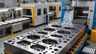
7 Best Plastic Injection Moulding Process Steps
-
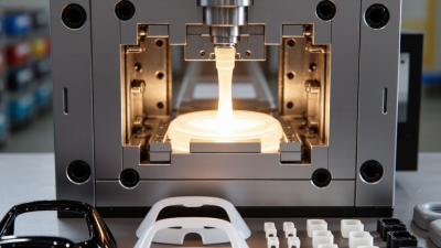
Why Choose the Plastic Injection Moulding Process?
-
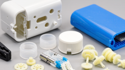
2026 Top Types of Plastic Injection Molded Parts?
-
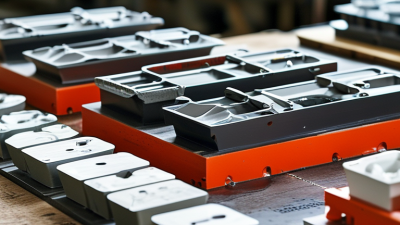
How to Choose a Plastic Injection Molding Supplier?
-
10 Best Plastic Injection Moulding Process Tips for Buyers
-
2026 Top Plastic Injection Moulding Process Innovations?